

Formwork and Reinforcement Drawings for Industrial Construction
Construction-ready drawings for foundations, floor slabs, walls and concrete levelsFormwork and reinforcement drawings turn the structural calculations into what gets built on site. In industrial construction they are crowded with anchors, embedded parts and openings from the process, piping and electrical design. INOPCO produces these drawings on the basis of our own structural design or one handed over to us.
We deliver formwork drawings, reinforcement drawings, placing instructions and steel quantities for tendering. Every change gets a revision index, so the right version is on site.
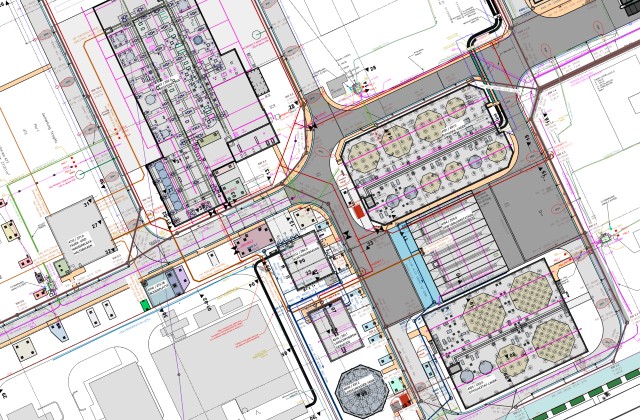
What formwork and reinforcement design covers
Formwork and reinforcement design is part of the construction documents, under the German HOAI work stage 5 of structural engineering. It defines the shape and reinforcement of each concrete member so that formwork, rebar and pouring can proceed without queries. The basis is EN 1992.
Coordination effort is higher in industrial projects than in building construction. A machinery foundation can have dozens of anchors, sleeves and openings from different disciplines. We bring this data together in one drawing.
What you receive
- Formwork drawings with dimensions, levels and openings
- Reinforcement drawings with bar marks and cover
- Placing and installation instructions
- Reinforcement quantities and bar bending schedules
- Drawing register with revision and status
Services in detail
What our drawings containFormwork drawings
Member outline with dimensions, levels, joints, openings and embedded parts as the basis for formwork.
Reinforcement drawings
Bar marks, diameters, spacing, laps and concrete cover, derived from the design.
Embedded parts coordination
Anchor plates, anchor bolts, sleeves and penetrations from process, building services and electrical design brought together.
Quantities for tendering
Concrete and reinforcement quantities as the basis for bills of quantities and bid comparison.
Revision and approval
Drawings with number, revision, date and status so that the valid version is always on site.
Sealing surfaces and bunds
Reinforcement and joints for liquid-tight concrete in AwSV installations. AwSV / WHG planning
Formwork and reinforcement in our projects
Foundations, existing levels and buildings in the process industry
Silo and conveyor bridge foundations
Formwork and reinforcement drawings, placing instructions and steel quantities for four new silos and the conveyor bridge.
View project
Concrete level in an existing plant
Recalculation of the concrete slab at +7.00 m and concrete drawings for openings and strengthening.
View project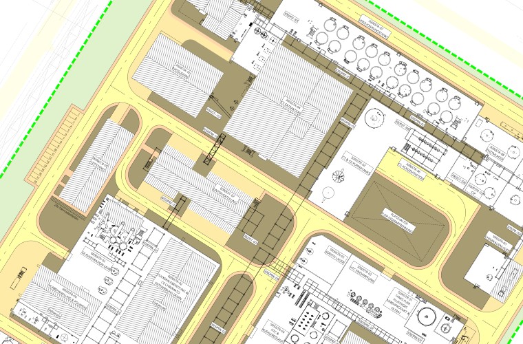
Buildings for a biorefinery
Concrete and structural design for the control building with laboratory and the main and sub-distribution stations.
View projectHow the drawings are produced
From calculations to approval1. Take over the design
Review our own or a handed-over design, clarify queries and define responsibilities.
2. Collect embedded parts
Gather anchors, sleeves and openings from all disciplines and check for clashes.
3. Produce drawings
Draw formwork and reinforcement with placing details and determine quantities.
4. Check and release
Submit drawings to the agreed checking and approval route and incorporate comments.
Related services: structural engineering for industrial facilities, steel structures and pipe racks, foundations for machinery, tanks and silos, execution planning and building permit and approval planning.