

Steel Structures and Pipe Racks for Industrial Facilities
Platforms, plant structures and pipe routes, calculated and designed to construction stageIn production plants, steelwork carries vessels, pipework and access levels, and it has to be adaptable years later. INOPCO designs steel structures for new and existing plants: calculations, construction drawings and steel quantities. On this basis, the steel contractor produces workshop and erection drawings, which we check against our design.
Pipe racks and pipe supports also take forces from pipe weight, contents, thermal expansion and friction. We agree these loads with the piping design before fixing sections and supports.

What steel structure design involves in industry
Steel structure design defines what a steel frame looks like, how it carries loads and how it is fabricated and erected. It covers the structural concept, calculations and construction drawings. Workshop and erection drawings, including connection design, are then produced by the steel contractor. The governing standards are EN 1993 and, for execution, EN 1090.
In industrial plants, steel structures rarely stand alone. They support columns, vessels, pumps and pipework and are modified again and again. We therefore plan reserves and connection points where future extensions are foreseeable.
Typical tasks
- Access platforms, stairs and landings
- Plant and column support structures
- Pipe racks and pipe supports
- Conveyor bridges and conveyor supports
- Strengthening and conversion of existing steelwork
Steel structure design services
From load assumptions to construction-ready drawingsCalculations and design
Design of beams, columns and bracing, prepared for independent checking, with internal forces as the basis for the contractor’s connection design.
Platforms and structures
Operating levels, maintenance platforms and plant structures matched to layouts, loads and access.
Pipe racks and supports
Structures for pipe routes with anchor and sliding points, based on load data from the piping design.
Existing plants
Survey and recalculate existing steelwork and strengthen it with new frames, columns or bracing.
Workshop drawing review
We check the steel contractor’s workshop and erection drawings against our calculations and construction drawings before fabrication.
3D model and coordination
Combine steelwork, equipment and pipework in one model, detect clashes and derive drawings.
Steelwork in our projects
New builds and conversions in chemicals, sugar and bioethanol plants
Column and DN900 line
A new distillation column integrated into existing steelwork, a DN900 roof penetration and updated permit calculations.
View project
New support frames for filters
New steel frames and opening trims at +7.00 m, strengthening from below and construction drawings for steelwork and concrete.
View project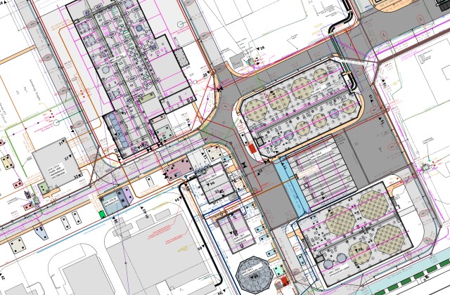
Pipe racks for a new permitted plant
For a new production facility in Saxony-Anhalt permitted under the BImSchG, we designed numerous pipe racks along with the steel and concrete structures, tendering and contract award.
View projectDesigning pipework and steelwork together
Most conflicts between pipework and steelwork arise at the supports. We therefore clarify early where anchor points sit, which movements sliding supports have to take and which forces go into the steel structure.
Loads we take into account
- Self-weight of pipe, insulation and contents
- Thermal expansion with anchor and sliding points
- Friction at sliding supports
- Wind, snow and maintenance loads
- Erection stages in existing plants
Example: DN900 vacuum vapour line
At a bioethanol plant, a new vertical DN900 line had to pass through the existing roof. We prepared the pipe stress analysis, carried the support forces into the permit calculations and designed the roof penetration.
What the steel contractor receives from us
The basis for workshop drawings, fabrication and erectionCalculations with internal forces
Sections, internal forces and support reactions as the basis for workshop drawings and connection design.
Construction drawings
General arrangements, sections and details with levels, grid lines and connection points.
Steel quantities
Quantities by item as the basis for tendering and contract award.
Related services: structural engineering for industrial facilities, foundations for machinery, tanks and silos, formwork and reinforcement drawings, execution planning and building permit and approval planning.